Scene Editor |
Scene Editor
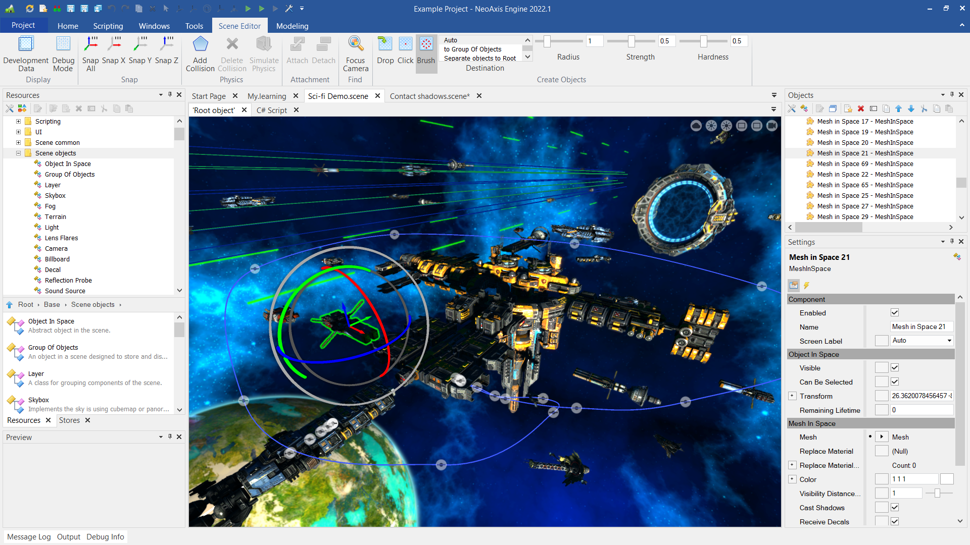
The scene editor is designed to edit 3D and 2D scenes.
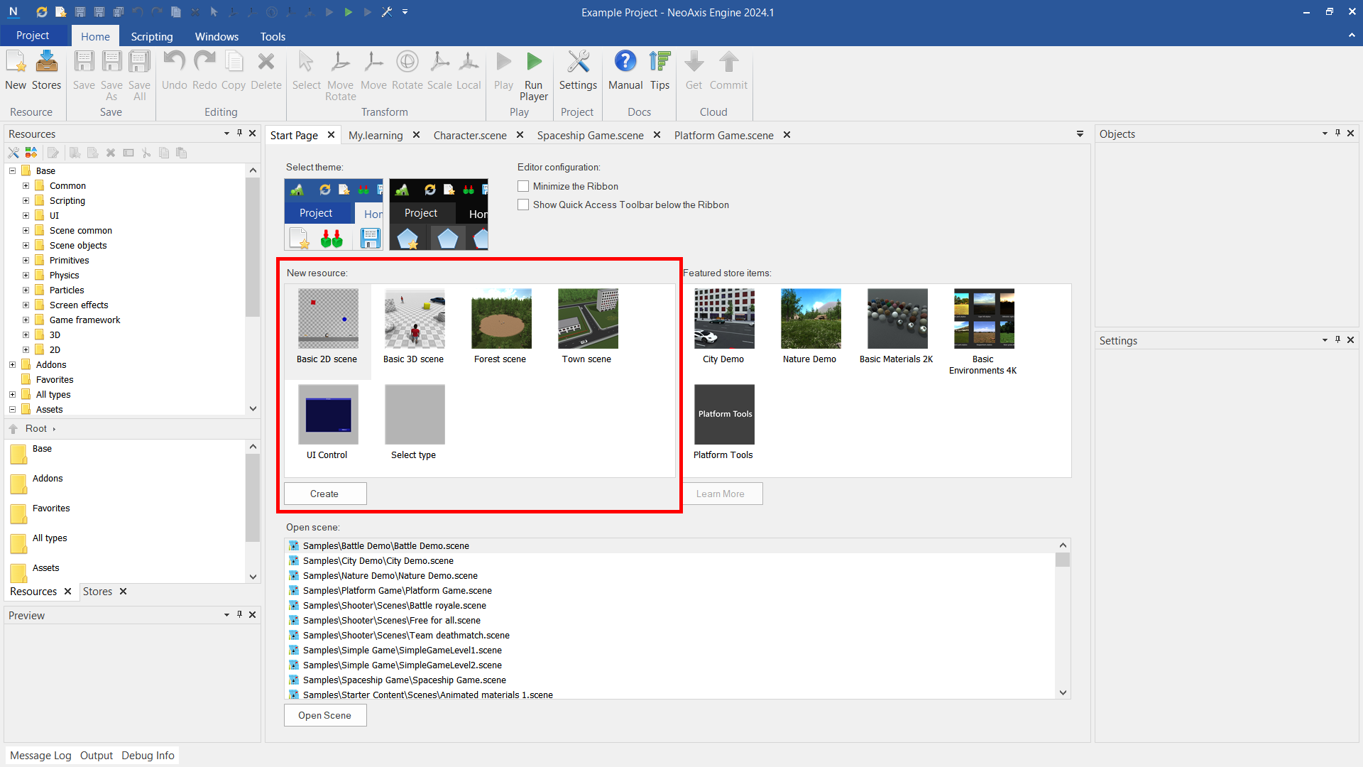
You can create a new scene from the Start Page. Double-click on the required scene template to create.
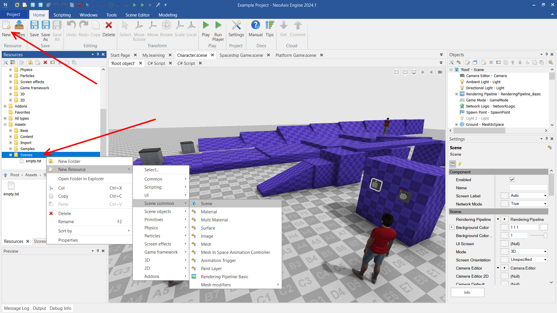
You can also create a new scene using the New button in the Ribbon and using the context menu of the Resource Window.
Learn more about creating resources.
The camera is controlled using the Q, W, E, A, S, D or arrow keys. For raising and lowering the camera, use Q, E, Page Up, Page Down keys. You can use the mouse to move the camera by holding the mouse wheel.
To rotate the camera, hold down the right mouse button.
The most convenient way to work with the camera is holding down the right mouse button to rotate and use Q, W, E, A, S, D keys to move.
You can focus the camera on the selected object using F key or using the "Focus Camera" button in the ribbon. By holding down F key and the right mouse button, you can rotate the camera around the selected object.
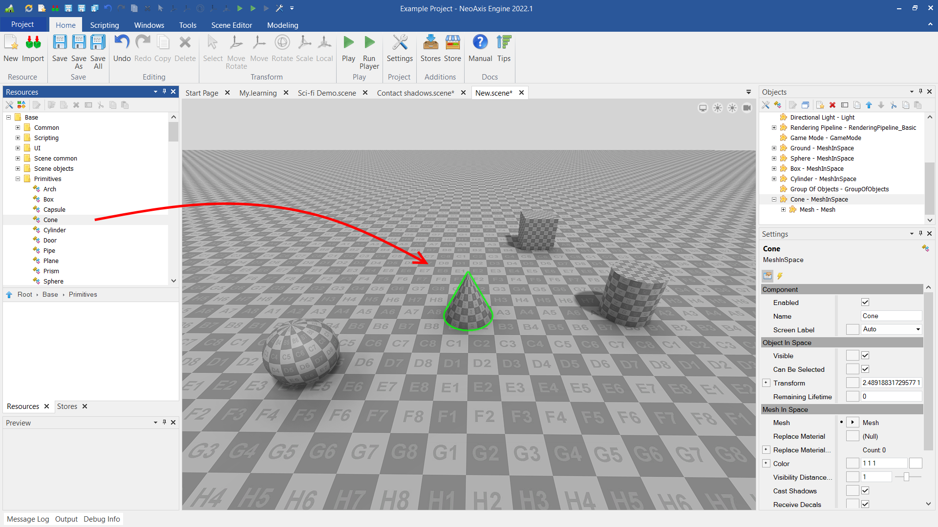
Basic way to create scene objects is through the Resources Window. Just pick a desired object and drag it to the scene.
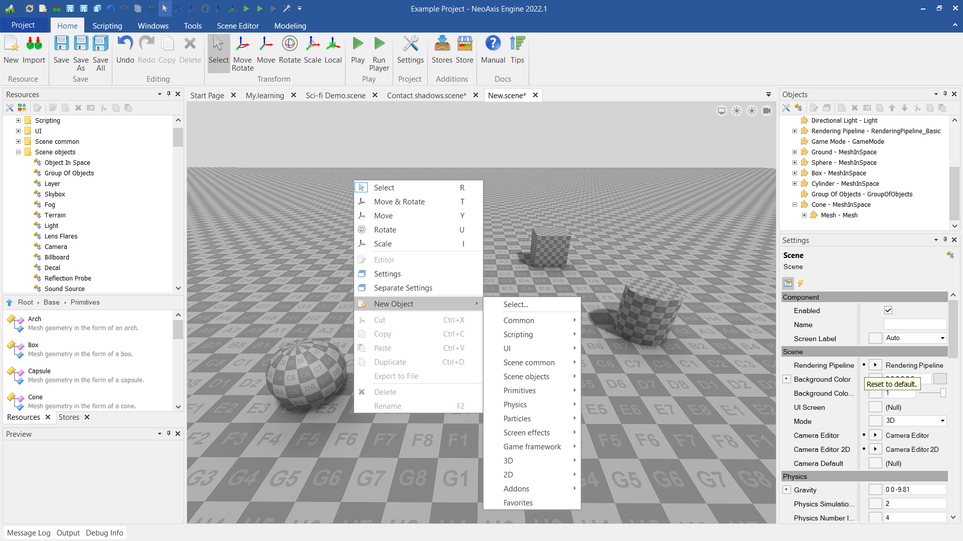
Another way to create an object is to use context menu.
Scene editor has many tools for object editing. There is the transform tool to transform position of the objects. "Scene Editor" tab in the Ribbon, where additional tools can be found.
You can also edit objects through Objects Window and Settings Window. These windows are intended to edit any other kind of resources as well.
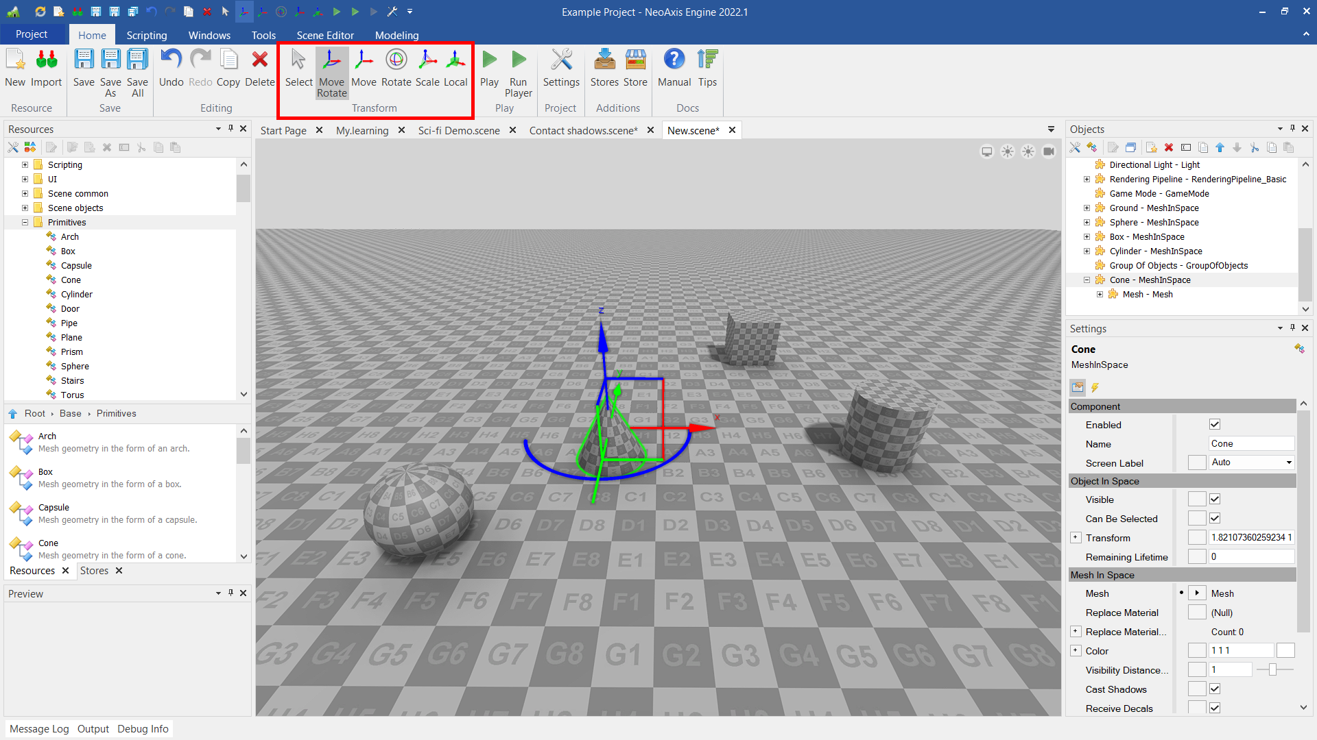
Once an object is selected, it can be modified with the transform tool. With this tool you can translate, rotate, or scale the objects.
The tool has five modes, which can be switched by clicking on the corresponding icon in the Ribbon, or by pressing R, T, Y, U, I keys. There is also a local coordinate mode.
| Name | Description |
|---|---|
 | Switches the control mode of the selected objects to the Select mode which allows to select objects only, without the possibility of their transformation. 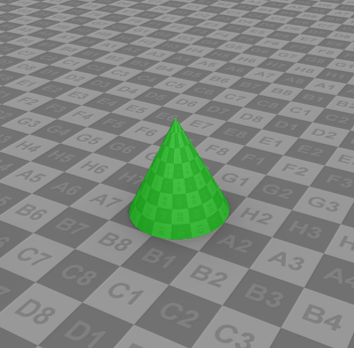 |
 | Switches the control mode of the selected objects to the Move & Rotate mode which allows to control the position and rotation by Z axis. 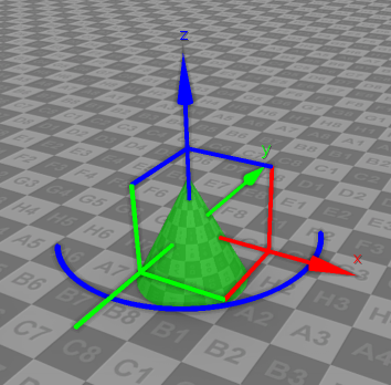 |
 | Switches the control mode of the selected objects to the Move mode which allows to control the position of the objects. 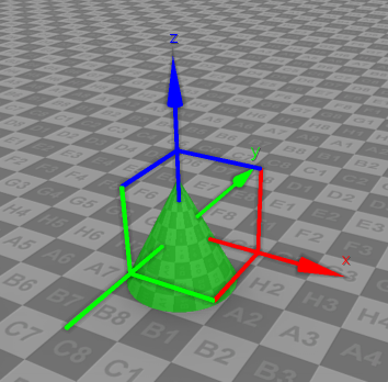 |
 | Switches the control mode of selected objects to the Rotate mode which allows to control the orientation of objects. When single object is selected then only this object can be rotated. When a group of objects is selected then the rotation occurs around a central point among all selected objects. 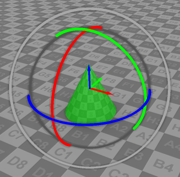 |
 | Switches the control mode of the selected objects to the Scale mode which allows to control the scale of objects. 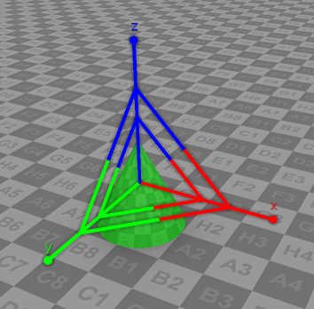 |
 | Switches the control mode of the selected objects to the transformation mode using the local coordinate system instead of the global one. The local coordinate system is based on the space of the object. |
When the scene editor is activated, "Scene Editor" tab appears in the Ribbon. The tab has additional tools for scene editing.

| Name | Description |
|---|---|
 | Allows configuring whether to display various additional data in the scene. 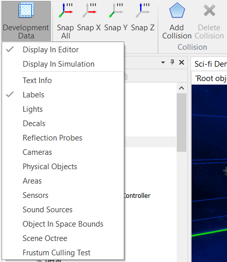 |
 | Changes the debug mode of the rendering pipeline. 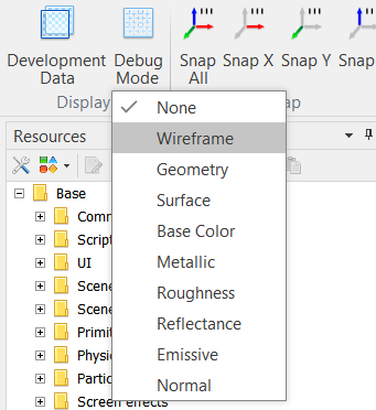 |
 | Align selected objects positions along all three axes. The step of alignment can be configured in Project Settings. |
 | Align selected objects positions along X axis. |
 | Align selected objects positions along Y axis. |
 | Align selected objects positions along Z axis. |
 | Adds physical body to selected objects. 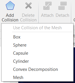 |
 | Removes physical body from selected objects. |
 | The mode to simulate physics for selected objects, to throw objects on the ground. Select object with the physical bodies, click the button. Next, to stop the simulation press Space or Return. |
 | Attaches one object to another. This button can't be pressed unless two or more objects are selected. |
 | Detaches selected objects between each other. |
 | Focuses the camera on the selected object. |
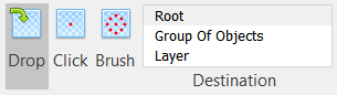
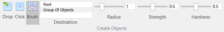
 | The mode of creating objects using the Drag and Drop method. |
 | The mode of creating objects by mouse clicking. |
 | The mode of creating objects with brush. |
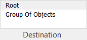 | A list of objects you can create objects within. The list may contain Root (scene), Group Of Objects, Layers. |
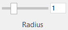 | Brush size. |
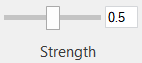 | Brush strength of impact. |
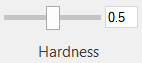 | Brush hardness. Determines the strength of impact depending on the distance to the center of the tool. |
In addition to the Drag and Drop method of creating, there are two more: creating by clicking and creating using a brush. Modes are switched in the Scene Editor tab.
Creating by clicking is almost the same as Drag and Drop mode. For its working, you need to select the created object in the Resources Window, then click the left mouse button in the workspace.
Creating with a brush is the third mode of creating objects. This mode is suitable for creating many objects. Brush options are specified in the ribbon tab.
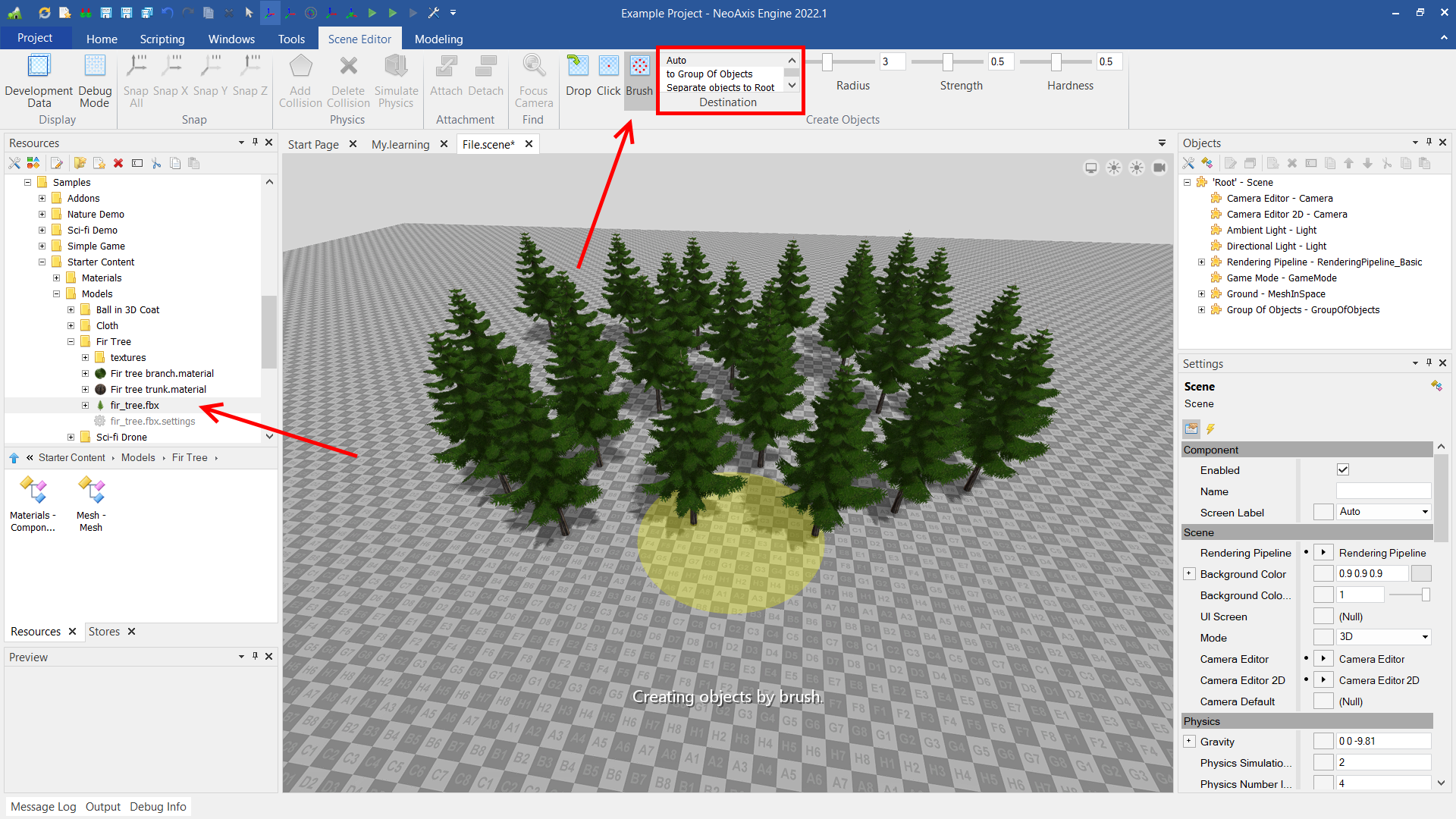
A brush is commonly used to create many objects of the same type. To effectively create many objects, there are special types in the editor Group Of Objects and Surface. The group of objects is a container for the effective management and display of many objects of the same type. Unlike objects created in the usual way, objects created in a group are not components. The surface is a template for creation of groups of objects, for example it is useful for nature creation.
Although the brush mode is not commonly used to paint meshes, it is good for a basic example.
In order to draw something with a brush, you first need to select the desired object to create in the Resources Window, for example, "Samples\Starter Content\Models\Fir Tree\fir_tree.fbx". In the tab, select Brush mode, also select "Group Of Objects" or "Auto" in the Destination list. A brush frame will appear in the workspace, after that you can draw.
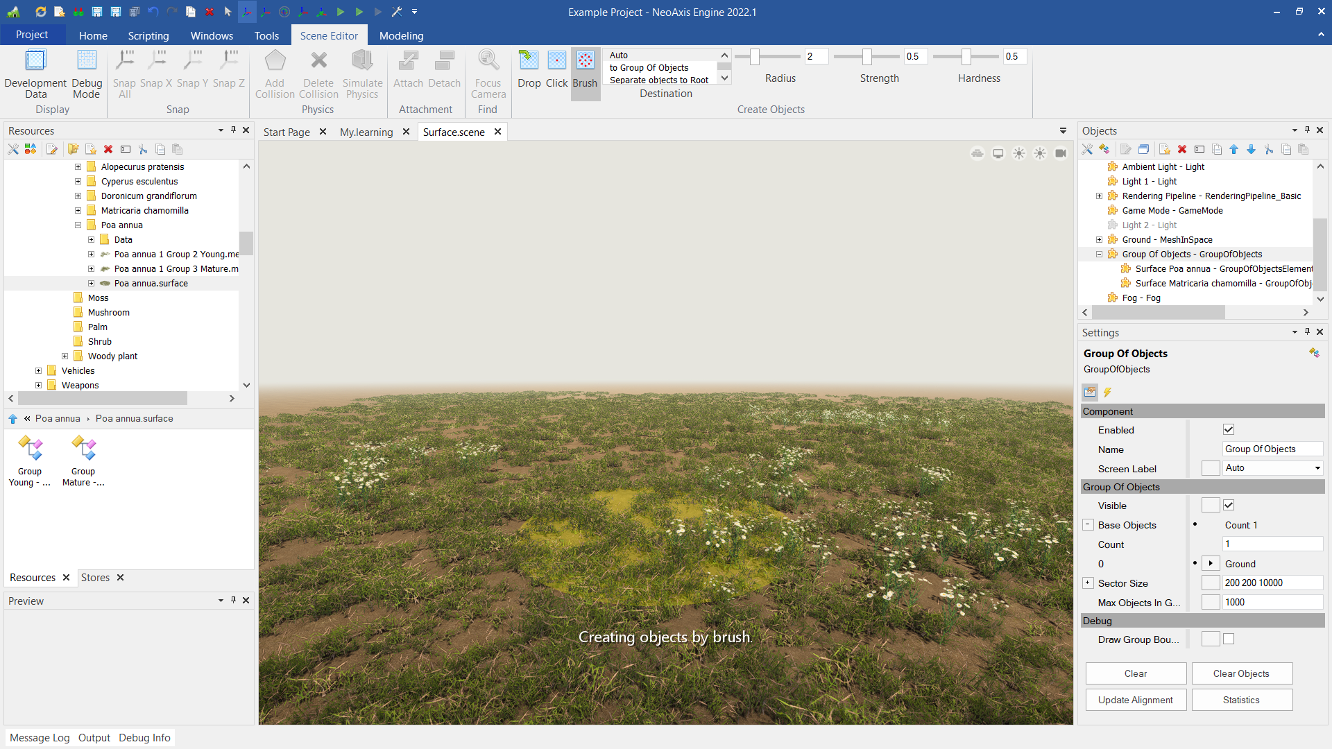
In order to draw into a group, it is necessary to configure its "Base Objects", the objects on which can paint. Learn more about it.
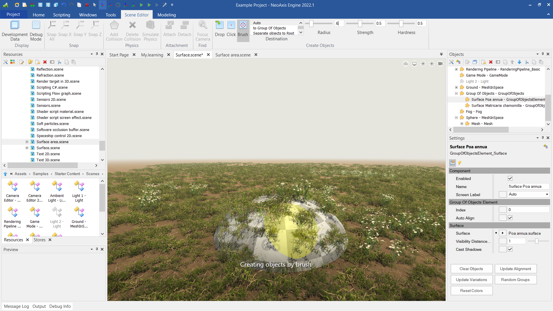
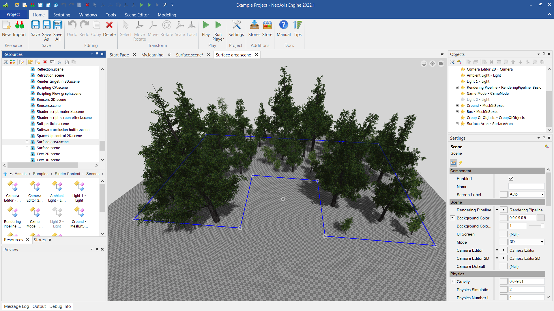
The best way to use brush mode it is using so-called surfaces, which are determined by Surface type. The type of surface, or the surface, determines which set of objects will be created during the drawing process and how exactly it will be created. For example, when creating vegetation, many of similar 3D models are usually used. Placed objects can have different sizes, random rotation. All this can be configured using the surfaces applied by brush.
You can find the example of the customized surfaces in "Content\Vegetation". The example scene is "Samples\Starter Content\Scenes\Surface.scene".
Learn more about the surfaces.
Learn more about vegetation creation.
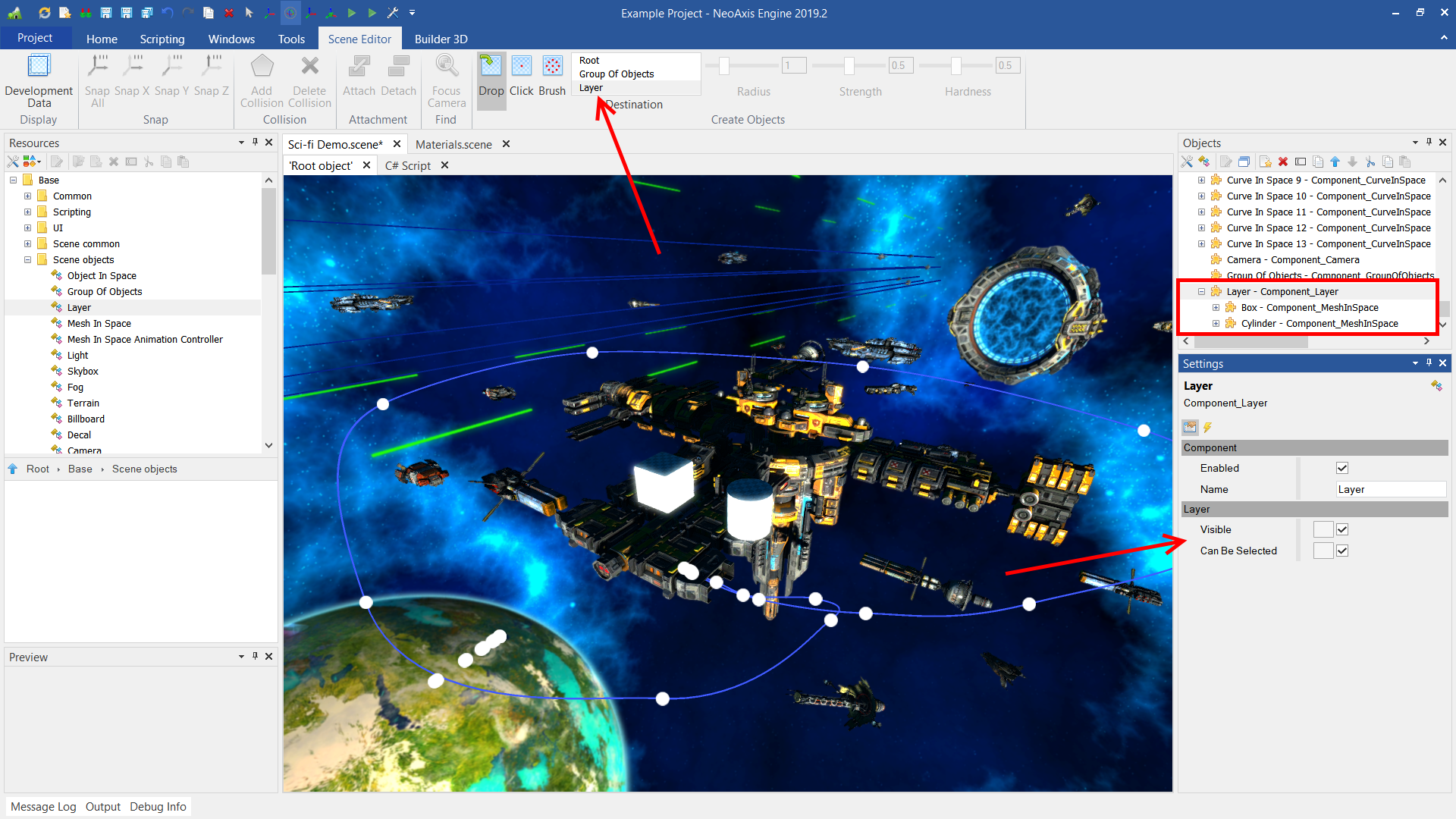
Objects can be grouped using layers. To place objects in a layer, you need to select the desired layer in the Destination list. New objects will be created in the selected layer.
You can hide layers and disable the ability to select objects in the work area. A layer object with nested objects can be found in the object tree in the Objects Window.
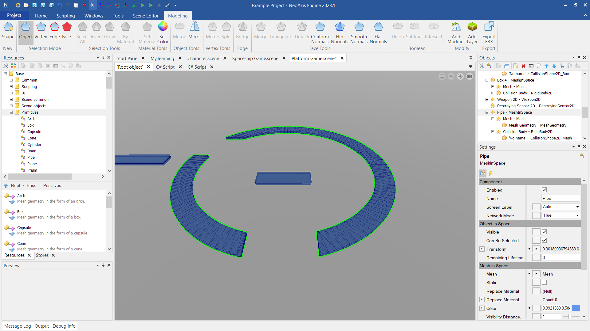
Modeling Tools is an extension of the scene editor, which includes fast level creation tools, 3D modeling, constructive solid geometry operations.
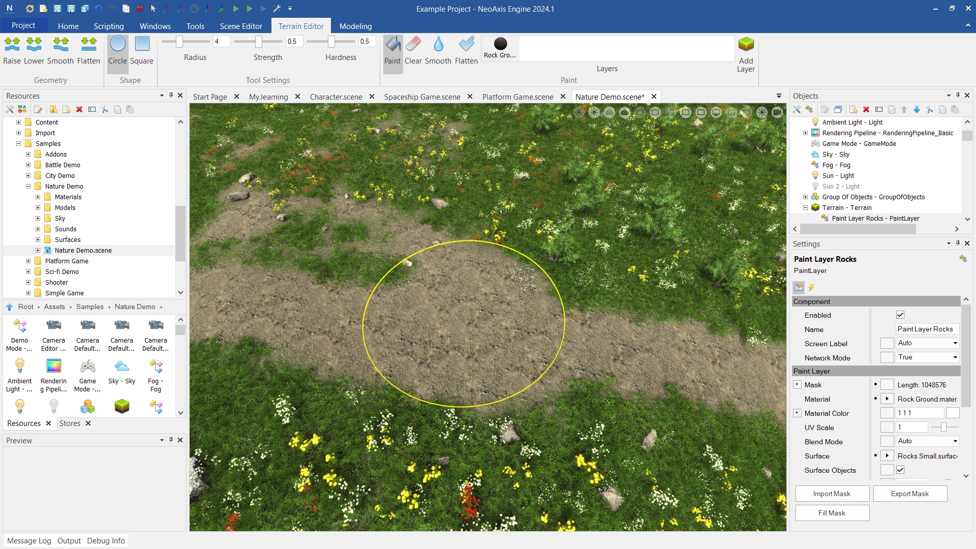
NeoAxis Engine has built-in height map based landscapes support. Read more.
Surface Area is used to automatically fill with a large number of objects in a given area.
| Name | Description |
|---|---|
| Q, W, E, A, S, D, arrows | Move camera. |
| R, T, Y, U, I | Change the mode of the transform tool. |
| F | Focuses the camera on the selected object. |
| Ctrl + C | Copy an object to a clipboard. |
| Ctrl + X | Copy an object to a clipboard for later transfer. |
| Ctrl + V | Paste an object from a clipboard. |
| Del | Delete selected objects. |
| Name | Description |
|---|---|
| Rendering Pipeline | The rendering pipeline of the scene. |
| Background Color | The background color of the scene. |
| Background Color Affect Lighting | Whether to affect the background color to ambient lighting. |
| UIScreen | The element of the user interface of the scene that will be used in a simulation. |
| Mode | The mode of the scene. |
| Screen Orientation | The way to override default screen orientation settings for the scene. The property is used for mobile devices. |
| Camera Editor | The camera used by the editor in 3D mode. |
| Camera Editor2 D | The camera used by the editor in 2D mode. |
| Camera Editor2 DPosition Z | Z position of the camera in 2D mode. |
| Camera Default | The default camera used. |
| Gravity | The gravity applied on the physical objects. |
| Wind Direction | The direction of the wind. |
| Wind Speed | The speed of the wind. |
| Physics Max Bodies | The max amount of bodies at the same time in the scene. Reopen the scene to apply changes. |
| Physics Advanced Settings | Whether to enabled advanced settings of the physics world. |
| Physics Default Convex Radius | In order to speed up the collision detection system, all convex shapes use a convex radius. The provided shape will first be shrunken by the convex radius and then inflated again by the same amount. |
| Physics Max Body Pairs | Maximum amount of body pairs to process (anything else will fall through the world), this number should generally be much higher than the max amount of contact points as there will be lots of bodies close that are not actually touching. Set for to auto mode. |
| Physics Max Contact Constraints | Maximum amount of contact constraints to process (anything else will fall through the world). Set 0 for auto mode. |
| Physics Max In Flight Body Pairs | Size of body pairs array, corresponds to the maximum amount of potential body pairs that can be in flight at any time. Setting this to a low value will use less memory but slow down simulation as threads may run out of narrow phase work. Set 0 for auto mode. |
| Physics Collision Steps | The amount of collision steps for one update. |
| Physics Step Listeners Batch Size | How many PhysicsStepListeners to notify in 1 batch. |
| Physics Step Listener Batches Per Job | How many step listener batches are needed before spawning another job. Set to 2147483647 (INT_MAX) if no parallelism is desired. |
| Physics Baumgarte | Baumgarte stabilization factor (how much of the position error to 'fix' in 1 update) (unit: dimensionless, 0 = nothing, 1 = 100%). |
| Physics Speculative Contact Distance | Radius around objects inside which speculative contact points will be detected (unit: meters). |
| Physics Penetration Slop | How much bodies are allowed to sink into eachother (unit: meters). |
| Physics Linear Cast Threshold | Fraction of its inner radius a body must move per step to enable casting for the LinearCast motion quality. |
| Physics Linear Cast Max Penetration | Fraction of its inner radius a body may penetrate another body for the LinearCast motion quality. |
| Physics Manifold Tolerance | Max squared distance to use to determine if two points are on the same plane for determining the contact manifold between two shape faces (unit: meter). |
| Physics Max Penetration Distance | Maximum distance to correct in a single iteration when solving position constraints (unit: meters). |
| Physics Body Pair Cache Max Delta Position | Maximum relative delta position for body pairs to be able to reuse collision results from last frame (units: meter). |
| Physics Body Pair Cache Cos Max Delta Rotation Div2 | Maximum relative delta orientation for body pairs to be able to reuse collision results from last frame, stored as cos(max angle / 2). Default: cos(2 degrees / 2). |
| Physics Contact Normal Cos Max Delta Rotation | Maximum angle between normals that allows manifolds between different sub shapes of the same body pair to be combined. Default: cos(5 degree). |
| Physics Contact Point Preserve Lambda Max Dist | Maximum allowed distance between old and new contact point to preserve contact forces for warm start (units: meter). |
| Physics Num Velocity Steps | Number of solver velocity iterations to run. Note that this needs to be >= 2 in order for friction to work (friction is applied using the non-penetration impulse from the previous iteration). |
| Physics Num Position Steps | Number of solver position iterations to run. |
| Physics Min Velocity For Restitution | Minimal velocity needed before a collision can be elastic (unit: m). |
| Physics Time Before Sleep | Time before object is allowed to go to sleep (unit: seconds). |
| Physics Point Velocity Sleep Threshold | Velocity of points on bounding box of object below which an object can be considered sleeping (unit: m/s). |
| Physics Constraint Warm Start | Whether or not to use warm starting for constraints (initially applying previous frames impulses). |
| Physics Use Body Pair Contact Cache | Whether or not to use the body pair cache, which removes the need for narrow phase collision detection when orientation between two bodies didn't change. |
| Physics Use Manifold Reduction | Whether or not to reduce manifolds with similar contact normals into one contact manifold. |
| Physics Allow Sleeping | If objects can go to sleep or not. |
| Physics Check Active Edges | When false, we prevent collision against non-active (shared) edges. Mainly for debugging the algorithm. |
| Gravity2 D | The gravity applied on the 2D physical objects. |
| Background Sound | Specifies background sound of the scene. Usually it is a music. |
| Background Sound Volume In Editor | Specifies background sound volume in the editor. |
| Background Sound Volume In Simulation | Specifies background sound volume in the simulation. |
| Sound Attenuation Near | The default minimum distance from the listener, after which the sound begins to weaken. |
| Sound Attenuation Far | The default maximum distance from the listener, after which no sound is heard. |
| Sound Rolloff Factor | The default damping factor. |
| Display Development Data In Editor | Whether to show development data in the editor. |
| Display Development Data In Simulation | Whether to show development data in the simulation. |
| Display Text Info | Whether to display text information of the development data. |
| Display Labels | Whether to display development data of the labels. |
| Display Lights | Whether to display development data of the lights. |
| Display Decals | Whether to display development data of the decals. |
| Display Reflection Probes | Whether to display development data of the reflection probes. |
| Display Cameras | Whether to display development data of the cameras. |
| Display Physical Objects | Whether to display physical objects. |
| Display Areas | Whether to display areas. |
| Display Volumes | Whether to display volumes. |
| Display Sensors | Whether to display sensors. |
| Display Sound Sources | Whether to display development data of the sound sources. |
| Display Object In Space Bounds | Whether to display the bounds of the objects in space. |
| Display Scene Octree | Whether to display the scene octree. |
| Frustum Culling Test | Enables the frustum culling test. |
| Octree Enabled | Enables the scene octree. |
| Octree Object Count Outside Octree To Rebuld | The number of objects to rebuild outside the octree. |
| Octree Bounds Rebuild Expand | The expand vector of the octree bounds. |
| Octree Min Node Size | The minimum node size of the octree. |
| Octree Object Count To Create Child Nodes | The number of objects needed to create child nodes. |
| Octree Max Node Count | The maximum number of nodes created by the octree. |
| First | Gets first enabled scene. |