Modeling Tools |
Modeling Tools
Modeling Tools is an extension of Scene Editor, which includes fast level creation tools, 3D modeling, constructive solid geometry operations. This is a tool for editing 3D models in the scene. Created models can be used both as scene objects and as ordinary 3D models.
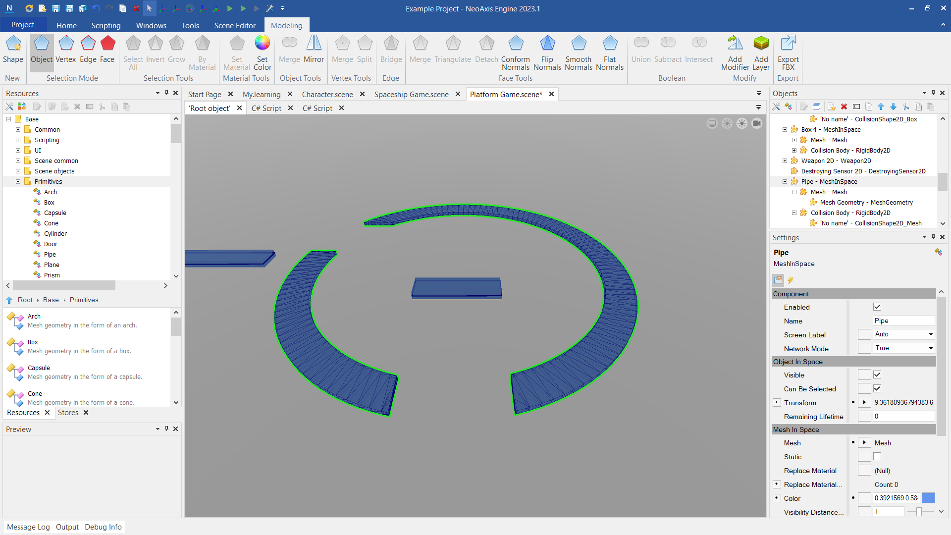
The editor is presented as the Modeling tab in the Ribbon. Using the tab, you can create shapes, switch the mode of selecting objects, and perform actions with objects.

First, the figures in the scene are created. There are two ways to do this.
Figures can be created in the standard way, using the window Resources Window. You need to select the desired shape in 'Base\Primitives' group, then drag and drop it into the editor workspace.

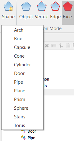
Figures can be created using the ribbon tab buttons.
| Name | Description |
|---|---|
 |  |
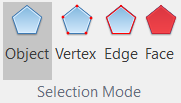
There are four modes of selecting objects, or, more simply, four modes of working.
| Name | Description |
|---|---|
 | Object selection mode. This is the usual scene editor mode, enabled by default. |
 | Vertex selection mode. In this mode you can select the vertices, move them, perform any editing actions.
The vertices are moved using the transformation tool, just as it is done with scene objects. 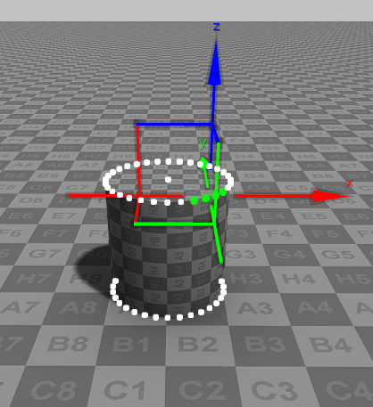 |
 | Edge selection mode. In this mode you can select the edges, perform any editing actions. |
 | Face selection mode. In this mode you can select the faces, perform any editing actions.
In the face mode there are base actions apart from the actions that are presented in the ribbon. You can clone and delete faces. Clone and Delete actions are available in the main tab of the ribbon, in the toolbar and in the context menu. 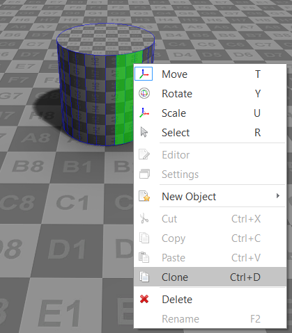 |
The main features of the editor are presented by actions.

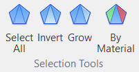
Operations for selecting objects.
| Name | Description |
|---|---|
 | Selects all elements. |
 | Selects all the elements that are not currently selected and removes selection from the currently selected elements. |
 | Adds adjacent elements to the currently selected elements. |
 | Selects all the faces that have the same material as currently selected faces. |
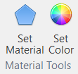
Operations for configuring materials.
| Name | Description |
|---|---|
 | Sets a material for the selected faces. The material to use has to be selected in the Resources Window. |
 | Sets a color for the selected objects. |
Operations for working with the figures.
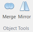
| Name | Description |
|---|---|
 | Combines the selected objects into a single one. If the single Mesh In Space object is selected than merges all child geometries into a single one. If several mesh objects are selected than places all child geometries of these objects into the single mesh object. |
 | Creates a mirror transformation of the selected object. |
Operations for working with the vertices.
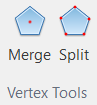
| Name | Description |
|---|---|
 | Merges selected vertices into the single vertex. This new single vertex can be placed at the center of the original vertices or at the first vertex position. |
 | Makes the vertices that are shared by many triangles independent. A new independent vertex is created for each triangle. |
Operations for working with the edges.
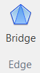
| Name | Description |
|---|---|
 | Connects two selected edges with a new face. If the edges have a common vertex then a single triangle is added. If the edges do not have a common vertex then two triangles are added. |
Operations for working with the faces.
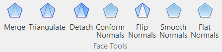
| Name | Description |
|---|---|
 | Combines selected faces into a single one. If the single Mesh In Space is selected then merges all the geometries into a single geometry. If several meshes are selected then replaces them by a single mesh and places all geometries into it. |
 | Splits selected faces to the separate triangles. Each triangle in a face will become a face. |
 | Removes selected faces from a geometry and places them in a new geometry. There are options:
|
 | Makes all normals in the mesh conformed to each other. There are two possible directions for conformed normals, which one to use is determined by the majority of triangles. |
 | Inverts the normals of selected faces. |
 | Recalculates the normals of selected faces to smooth them. |
 | Recalculates the normals of selected faces so that they do not have smoothing (perpendicular to the planes of the triangles). |
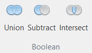
Boolean operations.
| Name | Description |
|---|---|
 | Implements constructive solid geometry union operation for two selected Mesh In Space objects. |
 | Implements constructive solid geometry difference operation for two selected Mesh In Space objects. The result object will be the first selected mesh minus the second selected mesh. |
 | Implements constructive solid geometry intersect operation for two selected Mesh In Space objects. |
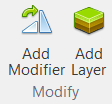
Modification operations.
| Name | Description |
|---|---|
 | Adds a mesh modifier to the object. Mesh modifiers provide the ability to modify the output data provided by the mesh; they do not change the original mesh data. 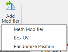 |
 | Adds a masked paint layer. |
Export functions.

| Name | Description |
|---|---|
 | Exports the selected 3D model to a FBX file. |
The created models can be used as normal 3D models in other scenes. The scene in which the object is created will be considered as a resource.
First, create one scene file and a figure in it.

Create the second scene. To place a 3D model from the first scene, you need to select the file of the first scene in the Resources Window. Next, expand it using the '+' button, find the desired figure and drag and drop it into the scene.

The functionality of modeling tools can be easy expanded. The developer can create own actions, mesh modifiers. The basic way to expand is to create your own mesh modifier.
Mesh modifiers are implemented as C# components, they available in the NeoAxis SDK:
- Sources\NeoAxis.CoreExtension\Modules\Mesh modifiers\MeshModifier_BoxUV.cs
- Sources\NeoAxis.CoreExtension\Modules\Mesh modifiers\MeshModifier_RandomizePosition.cs