Flow Graph Editor |
Flow Graph Editor
Flow Graph Editor is a node-based editor, that allows to adjust the interactions between objects visually.
The editor can be used for various purposes, for example, for scripting project logic. You can create event handlers, code methods.
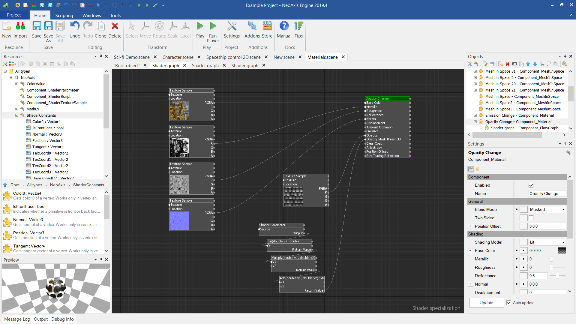
Also the editor can be used as a base for other specialized editors. For example, in the engine, graph editor used in the Material Editor.
The process of the creation and configuration of Flow Graph will be described by creating an event handler. Visual script will be created, which will be called during scene initialization. Precisely, the method of adding a message to the Player App console will be invoked when the scene is initialized.
To begin, create a scene. Next, you need to select the scene object, in Settings Window go to the Events tab. Then click on the add handler button. In this case, we need an Enabled Event (scene enable event).

After clicking on the button, a context menu appears in which you need to select the creation of Flow Graph.

The graph editor opens. It will have one Event Handler node.
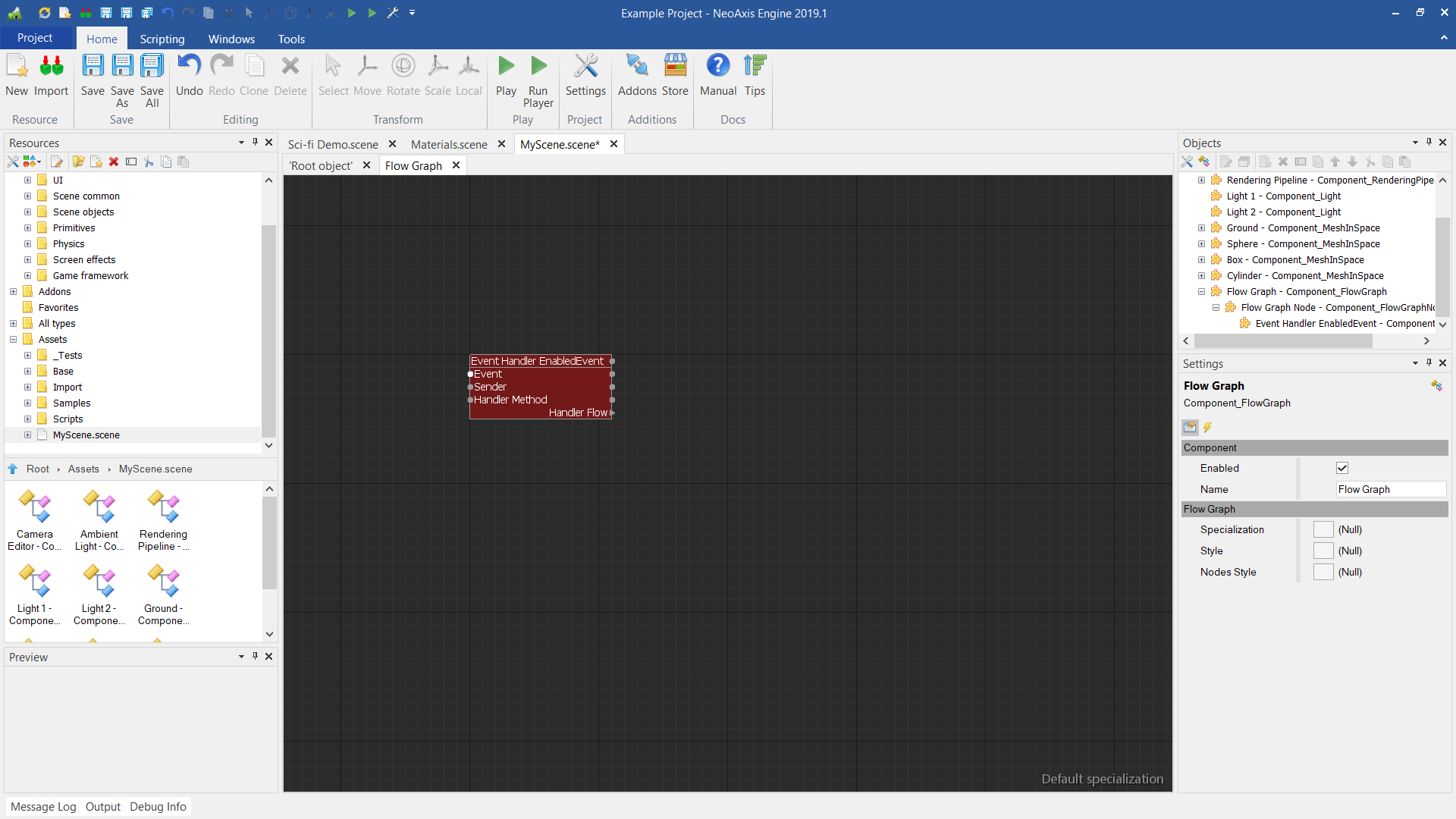
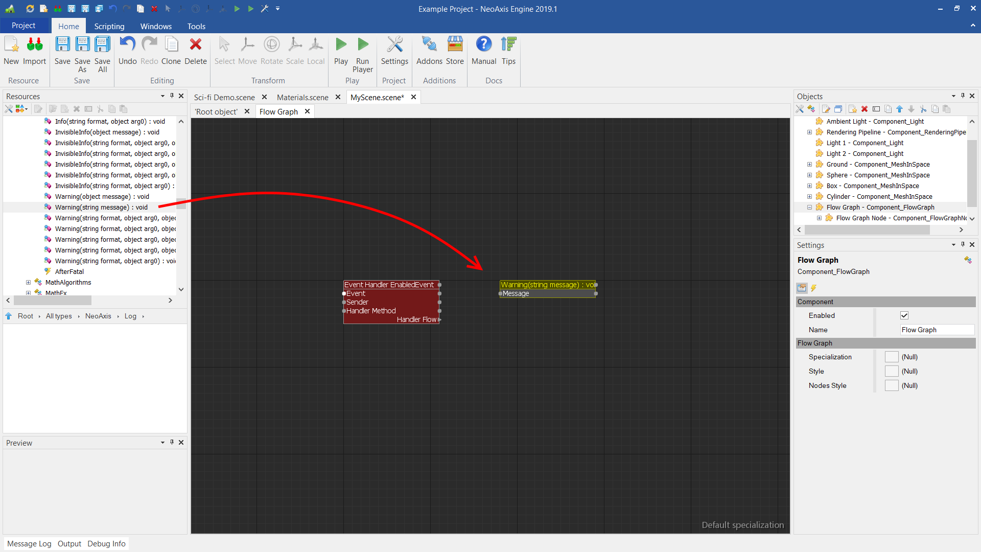
Next, attach another node to it with a call to the Log.Warning method. To do this, find the Log.Warning method in Resources Window, and drop it into the workspace. The method can be found at All types\NeoAxis\Log.
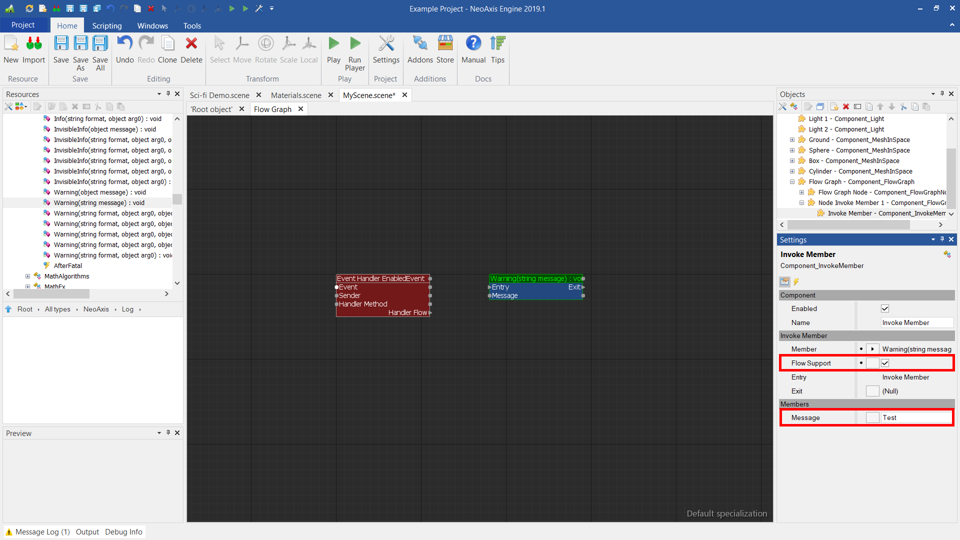
Now you can adjust the properties of the new node. In order to be able to connect the node with others, property Flow Support should be set to True. Fill in the Message parameter.
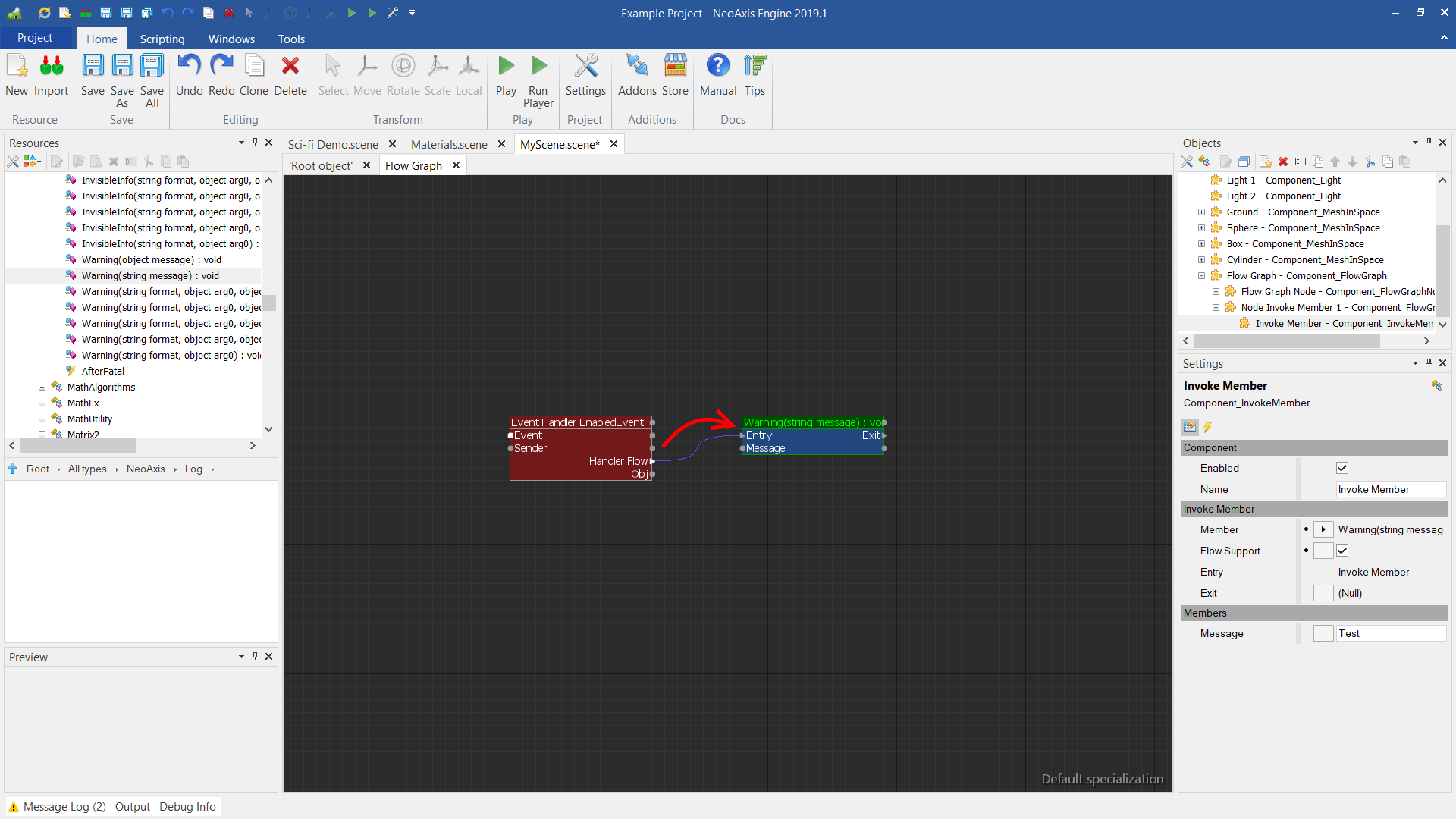
Next, connect the first node's Handler Flow output to the second Entry input.
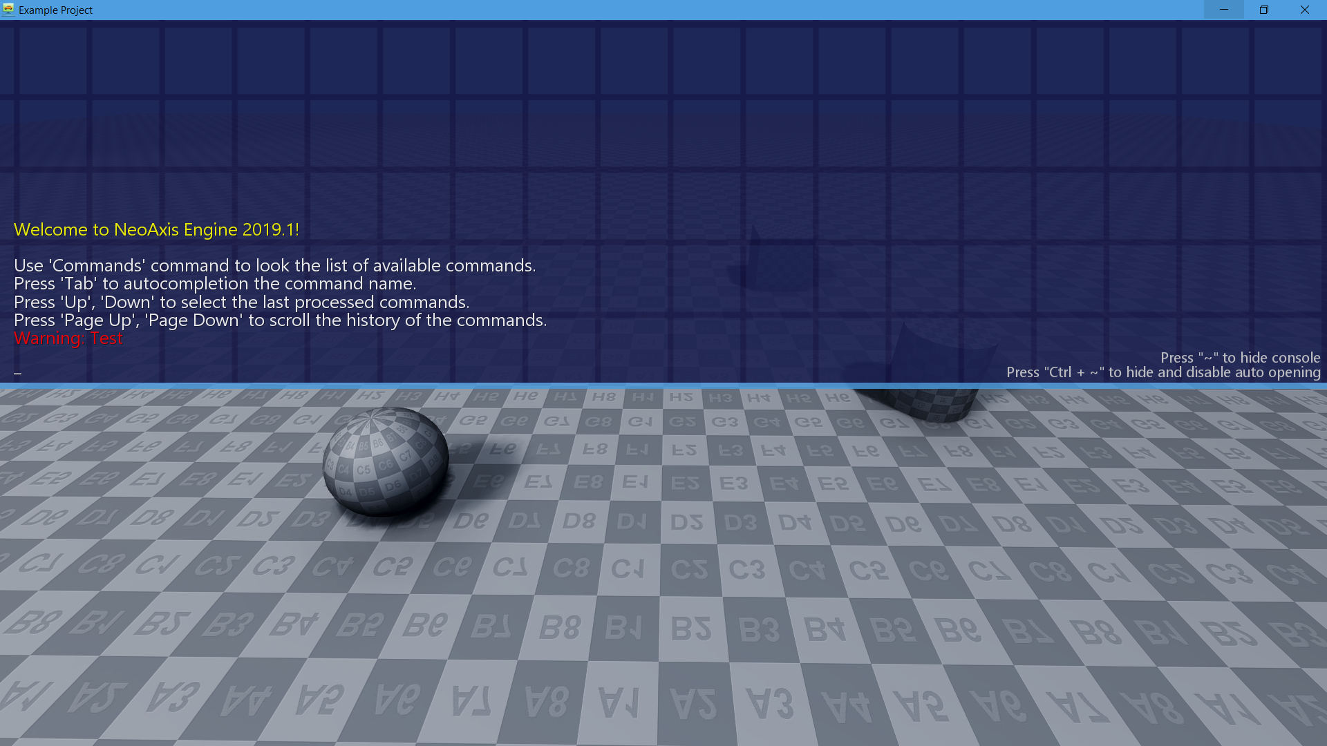
Now you can start the player (Play button in the Ribbon). A message will be displayed on the Player app console.
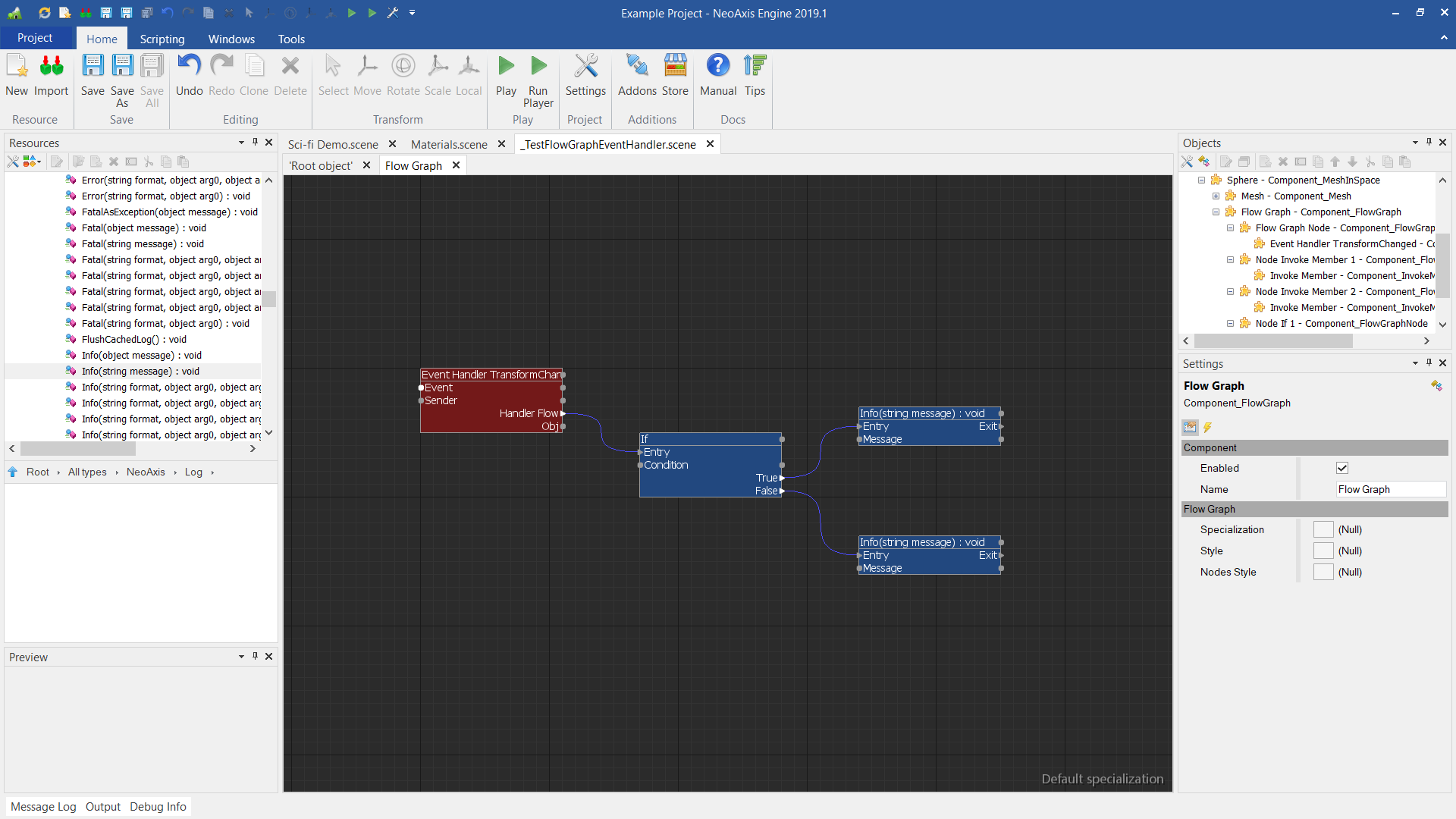
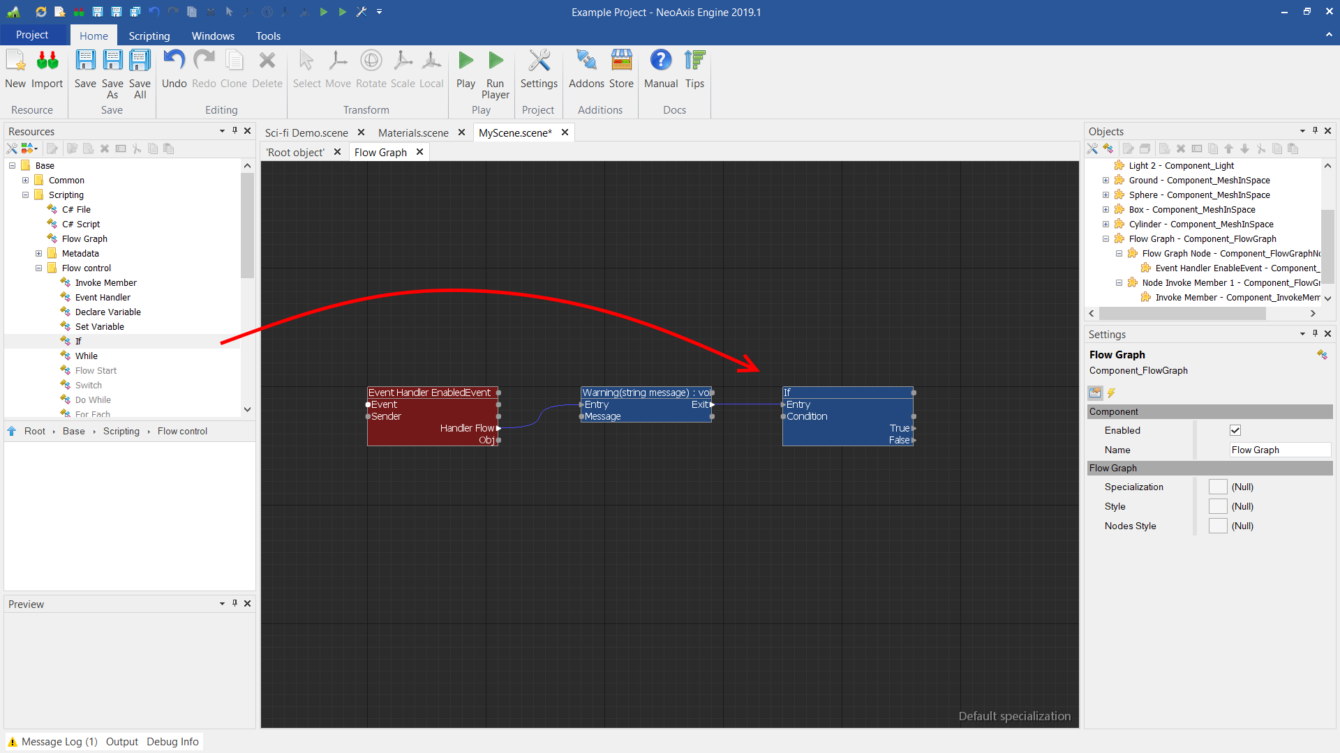
There are some control flow objects available. For example, If, While. These objects are located in the Resources Window, in the Base\Scripting\Flow control group.
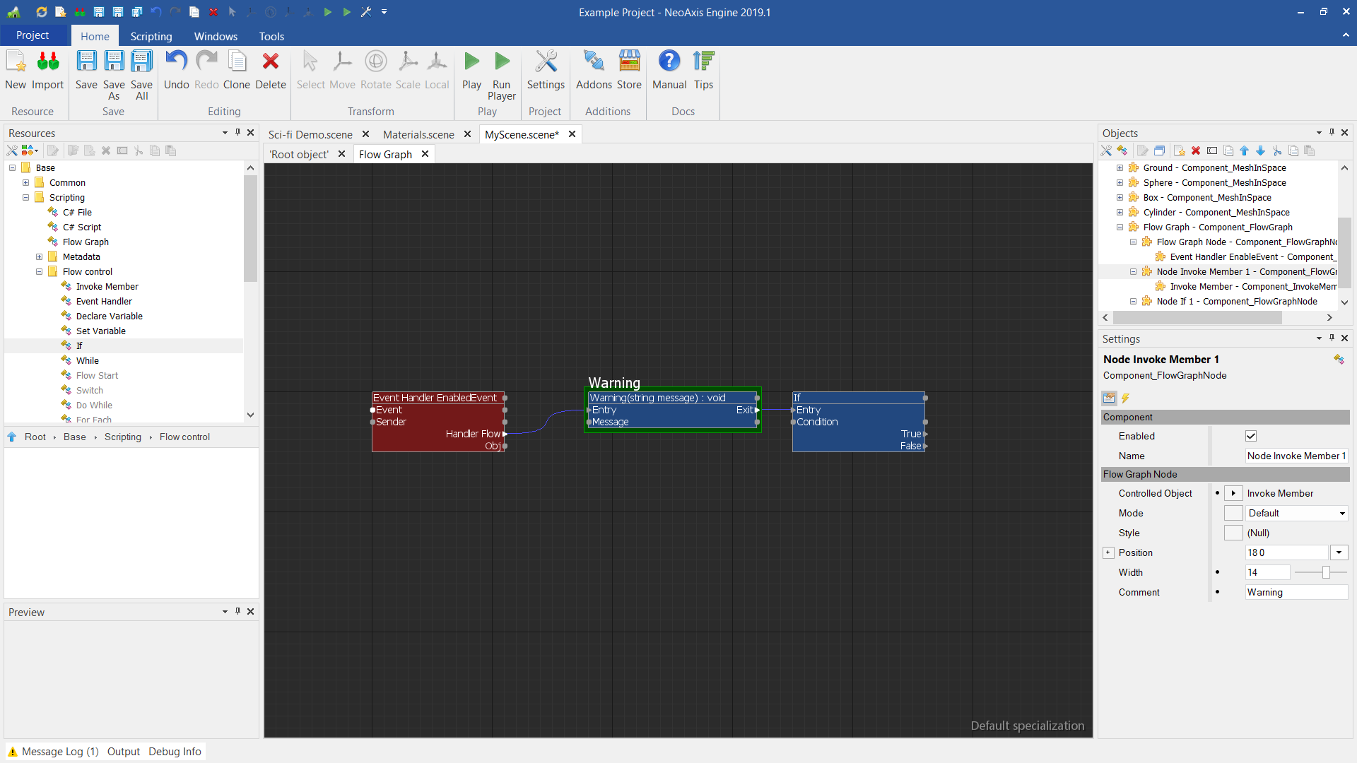
Nodes can be customized. For example, one can change their width, or add comments.
To do this, select the necessary nodes by the selection rectangle. You need to select it with the selection rectangle, since with a point click, it is not the node itself that is allocated, but the object inside the node.

The result of changing the settings.
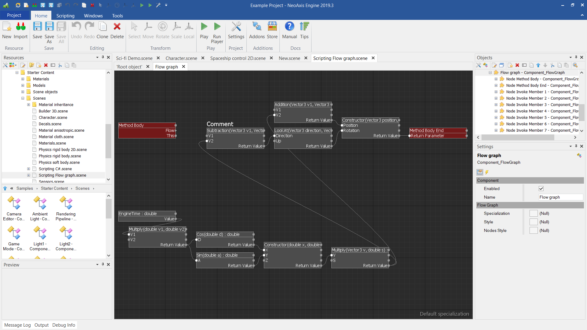
Samples\Starter Content\Scenes\Scripting Flow graph.scene
- Creating a virtual method with Flow Graph.
- Object property value calculating with Flow Graph.